 English
 Español
Super low loss amorphous transformers By using Amorphous Metal, the Core Loss (NLL) of a Transformer can be reduced by a whopping 75% - resulting in enormous energy savings.
Technical specification
- GENERAL TECHNICAL INFORMATION
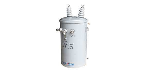
- Power Range kVA: 3. 5, 10, 15, 25, 37, 50, 75, 100, 167, 250, 333, 500
- Temperature Rise: 55°C or 65°C
- Cooling type : ONAN, OA,
- Frequency: 50Hz or 60Hz
- Polarity : Additive or Subtractive
- Primary Voltage : 2400V through 34500 GrdY / 19920V
- Secondary Voltage : 120 / 240V, 240 / 480 V, 277V, 600V
- Insulation Class : 2.4Kv~34.5kV (150kV BIL) and below
- Taps: none, or as an option, 4 x 2,5% HV
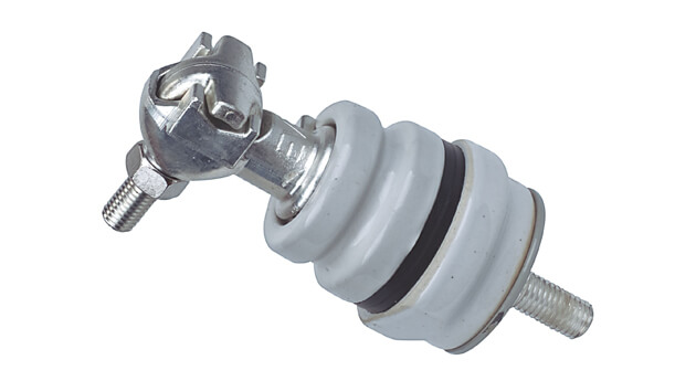
- HV Bushings: cover and sidewall mounted available
- STANDARD FEATURES
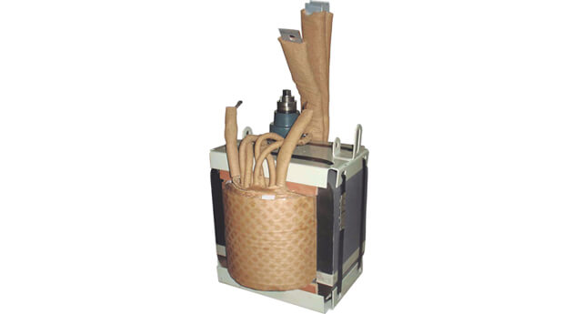
- −−Core and coils designed for an optimum Total Ownership Cost (TOC)
- −−Wound core with step-lap joints for increased efficiency and lower noise levels
- −−“Low-high-low” windings for increased short circuit strength, efficiency and thermal strength
- −−“Low-high-low” windings for increased short circuit strength, efficiency and thermal strength
- −−Computer aided design for mechanical & electrical calculations (C.A.D.)
- −−Paint system meeting or exceeding the performance of the IEEE C57.12.28 Standard
- −−Lifting lugs meeting all of the requirements of the CSA C2.1-06 and CSA C2.2-06 Standard
- −−Multiple cover clamps to ensure proper sealing and to mini-mize water retention on the cover edge
- −−Cover or sidewall mounted high voltage bushing(s) as required
- −−Low voltage spade or clamp type (basket) terminals as required
- −−Provision for surge arrester bracket, bracket available as an option
- −−Automatic self-resealing pressure relief valve
- OPTIONAL PRODUCT ACCESSORIES
- Cold-Rolled Grain Oriented Silicon Steel Core (CRGO) or Amorphous Metal Core (AMDT)
- Stainless Steel Tanks and Cover
- Extra Creep Bushing
- Surge Arrester Bracket
- The CSP protection package consists of four related components: H.V Fuse Link, Secondary Breaker, Signal light, External Surge Arrester that work together to provide complete self-contained protection against surge currents, short circuits and overloads.
- Units can be customized to specific requirements
| KVA | H.V. | Taps | L.V. | Loss(W) | DIMENSION(mm) | E | Weight(kg) | ||||
| Core | Winding | A | B | C | D | ||||||
| 5 | 13200/7620 or 11000/6350 | ±2×2.5% or 0 | 120 240 480 or 120-240 240-480 | 8 | 75 | 840 | 400 | 480 | 310 | 286 591 | 70 |
| 10 | 12 | 120 | 864 | 430 | 510 | 340 | 10 | ||||
| 15 | 15 | 195 | 914 | 430 | 510 | 340 | 125 | ||||
| 25 | 18 | 290 | 1041 | 480 | 560 | 380 | 162 | ||||
| 37.5 | 30 | 360 | 1120 | 520 | 610 | 450 | 240 | ||||
| 50 | 32 | 500 | 1245 | 520 | 610 | 450 | 295 | ||||
| 75 | 45 | 650 | 1245 | 600 | 680 | 510 | 420 | ||||
| 100 | 50 | 850 | 1270 | 640 | 710 | 510 | 465 | ||||
| 167 | 65 | 1410 | 1470 | 940 | 840 | 610 | 650 | ||||
Standards
IEEE C57.12.00,
ANSI C 57.12.20
IEC 60076
Certificate
ISO 9001
ISO 14001

The cores of conventional transformers consist of stacks of laminations that are made from silicon steel with an almost uniform crystalline structure (CRGO). In transformers with amorphous cores, a ribbon of steel is wound forming the core. The big benefit of amorphous metal core transformers is that amorphous steel has lower hysteresis losses. Simply put this means that less energy is wasted in magnetising and demagnetising it during each cycle of the supply current. The infrared pictures (above) illustrate this: The AMT core (left) shows a lot less heat than the CRGO core (right).
Advantage and Applications
Up to 75% energy saving over conventional silicone steel (CRGO)
Reduced carbon dioxide emissions
Reduction in fossil fuel consumption
Reduced magnetising current
Reduced magnetising current
Product Overview


Learn More...
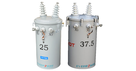
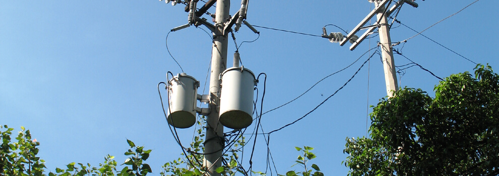
BIL95KV Single Phase Pole Mounted Transformer
pole-mounted Conventional type transformer 7200/12470Y, 7620/13200Y, 8320/14400Y
BIL95KV Single Phase Pole Mounted Transformer
Download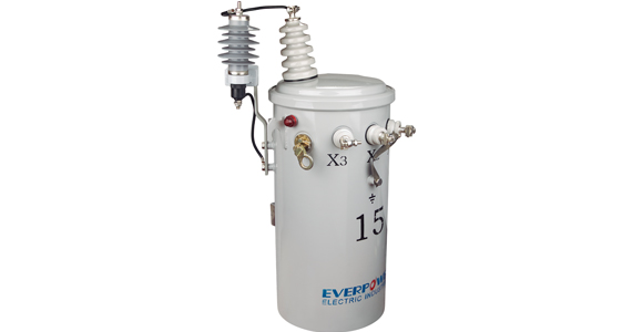
Single Phase CSP and CP Transformers
csp transformer, pole type transformer, overhead transformer, ansi transformer,single-phase, pole-type,kva transformers
Single Phase CSP and CP Transformers
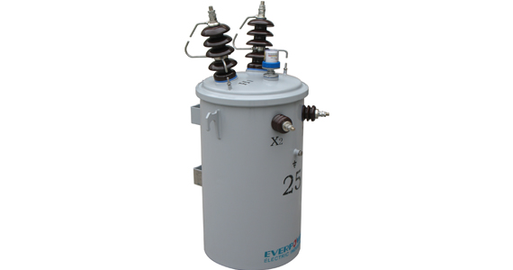
11KV IEC pole mounted transformers
11kv transformer,iec single-phase transformer, pole-mounted transformer